


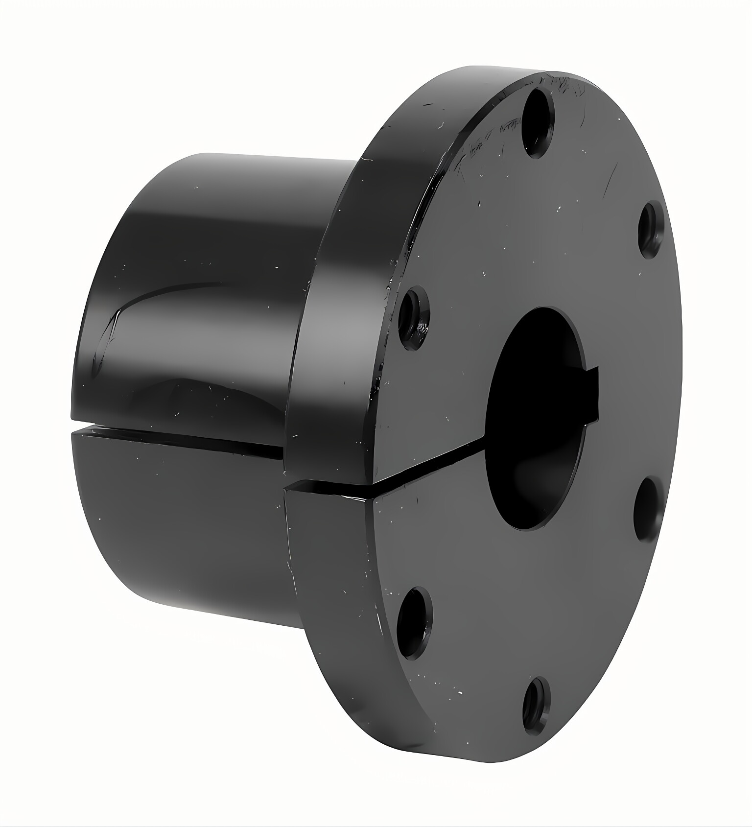
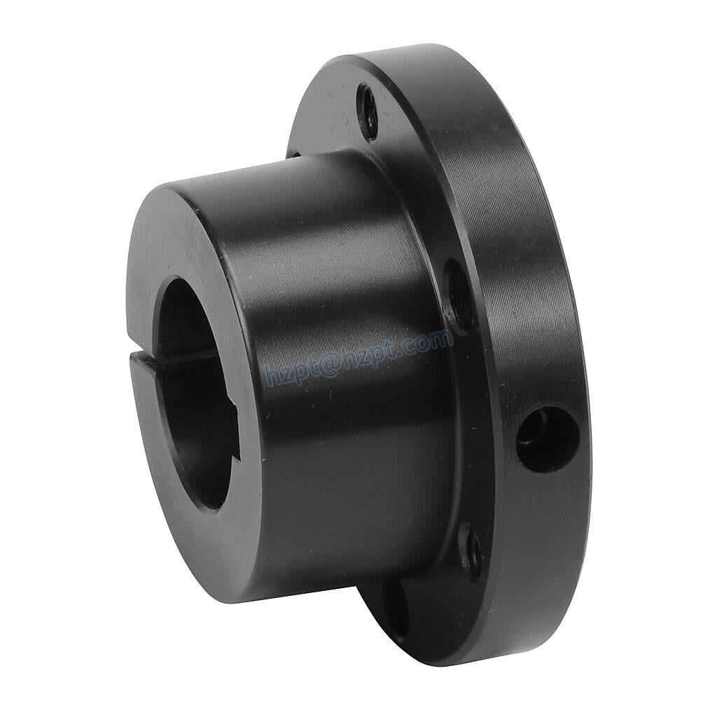
5V Series Cast Iron Eight-Groove QD Sheaves for "5V" Belts
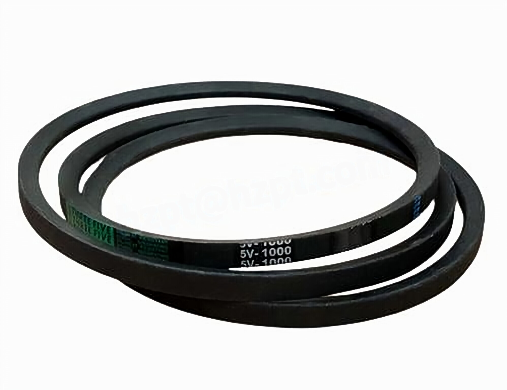
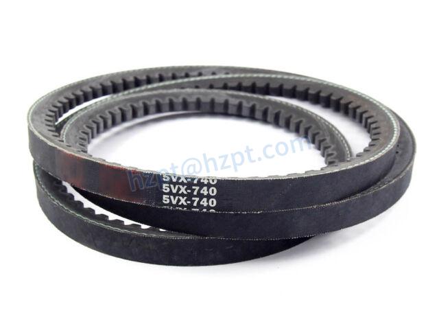
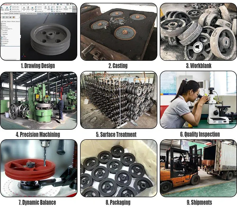
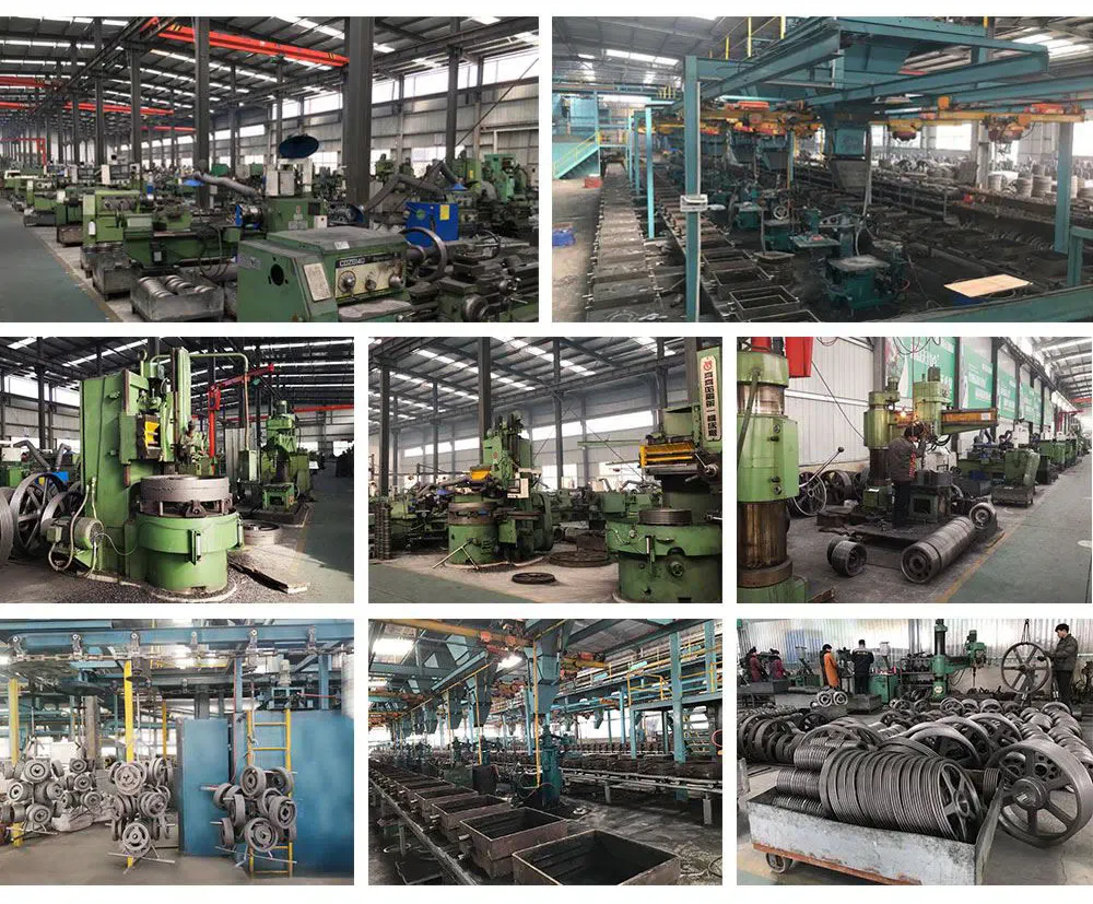
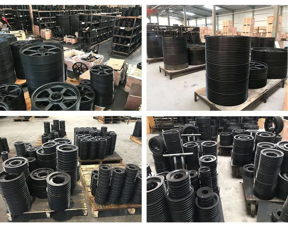
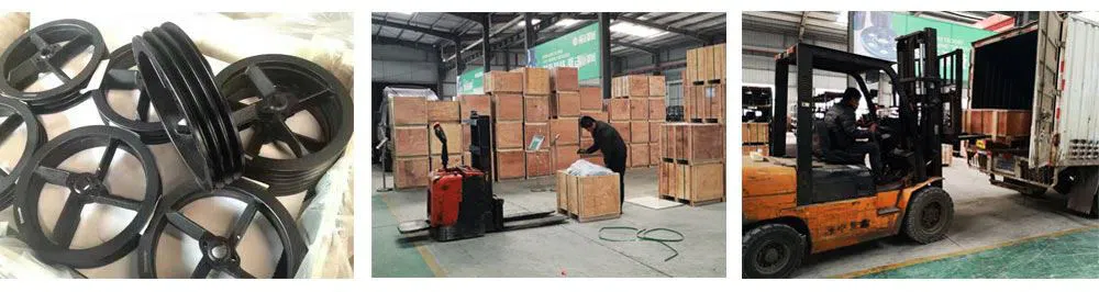
5V series eight-groove QD (quick detachable) bushed sheaves are manufactured for 5V, 5VX, banded 5V, and banded 5VX belts. They range from 4.40" to 50.00" in diameter. Depending on the sheave size, they are made to use an SF, E, F, J, or M QD bushing, which we also stock. Most of our eight-groove 5V QD sheaves are manufactured from a high-strength grade 35 cast iron, are phosphate-coated, and are painted for anti-corrosion. All of them are balanced at the factory for smooth machinery operation.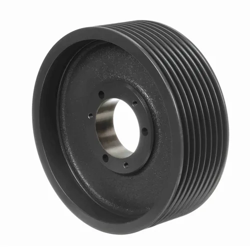
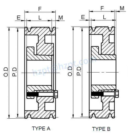
Size | Bushing Type | Type | Pitch Diameter | Outside Diameter | (E) | (F) | (L) | (M) | Weight (LBS) |
|---|---|---|---|---|---|---|---|---|---|
| 85V710SF | SF | A | 7.00" | 7.10" | 1 9/32" | 5 13/16" | 2 1/16" | 2 15/16" | 24.7 |
| 85V750SF | SF | A | 7.40" | 7.50" | 1 9/32" | 5 13/16" | 2 1/16" | 2 15/16" | 28.2 |
| 85V800E | E | A | 7.90" | 8.00" | 1 11/32" | 5 13/16" | 2 3/4" | 1 23/32" | 35.0 |
| 85V850E | E | A | 8.40" | 8.50" | 1 11/32" | 5 13/16" | 2 3/4" | 1 23/32" | 37.2 |
| 85V900E | E | A | 8.90" | 9.00" | 1 7/32" | 5 13/16" | 2 3/4" | 1 23/32" | 42.0 |
| 85V925F | F | A | 9.15" | 9.25" | 1 7/32" | 5 13/16" | 3 3/4" | 27/32" | 44.0 |
| 85V975F | F | A | 9.65" | 9.75" | 1 7/32" | 5 13/16" | 3 3/4" | 27/32" | 48.4 |
| 85V1030F | F | A | 10.20" | 10.30" | 1 7/32" | 5 13/16" | 3 3/4" | 27/32" | 58.4 |
| 85V1090F | F | A | 10.80" | 10.90" | 1 7/32" | 5 13/16" | 3 3/4" | 27/32" | 63.1 |
| 85V1130F | F | A | 11.20" | 11.30" | 1 7/32" | 5 13/16" | 3 3/4" | 27/32" | 67.0 |
| 85V1180F | F | A | 11.70" | 11.80" | 1 7/32" | 5 13/16" | 3 3/4" | 27/32" | 71.0 |
| 85V1250F | F | A | 12.40" | 12.50" | 1 7/32" | 5 13/16" | 3 3/4" | 27/32" | 76.0 |
| 85V1320F | F | A | 13.10" | 13.20" | 1 7/32" | 5 13/16" | 3 3/4" | 27/32" | 80.0 |
| 85V1400F | F | A | 13.90" | 14.00" | 1 7/32" | 5 13/16" | 3 3/4" | 27/32" | 81.0 |
| 85V1500F | F | A | 14.90" | 15.00" | 1 7/32" | 5 13/16" | 3 3/4" | 27/32" | 83.0 |
| 85V1600F | F | A | 15.90" | 16.00" | 1 7/32" | 5 13/16" | 3 3/4" | 27/32" | 90.0 |
| 85V1870J | J | A | 18.60" | 18.70" | 1/8" | 5 13/16" | 4 5/8" | 1 1/16" | 120.0 |
| 85V2120J | J | A | 21.10" | 21.20" | 1/8" | 5 13/16" | 4 5/8" | 1 1/16" | 152.0 |
| 85V2360J | J | A | 23.50" | 23.60" | 1/8" | 5 13/16" | 4 5/8" | 1 1/16" | 185.0 |
| 85V2800J | J | A | 27.90" | 28.00" | 1/8" | 5 13/16" | 4 5/8" | 1 1/16" | 210.0 |
| 85V3150M | M | B | 31.40" | 31.50" | 11/32" | 5 13/16" | 6 3/4" | 1 9/32" | 242.0 |
| 85V3750M | M | B | 37.40" | 37.50" | 11/32" | 5 13/16" | 6 3/4" | 1 9/32" | 285.0 |
| 85V5000M | M | B | 49.90" | 50.00" | 11/32" | 5 13/16" | 6 3/4" | 1 9/32" | 408.0 |
 |  |
 |  |
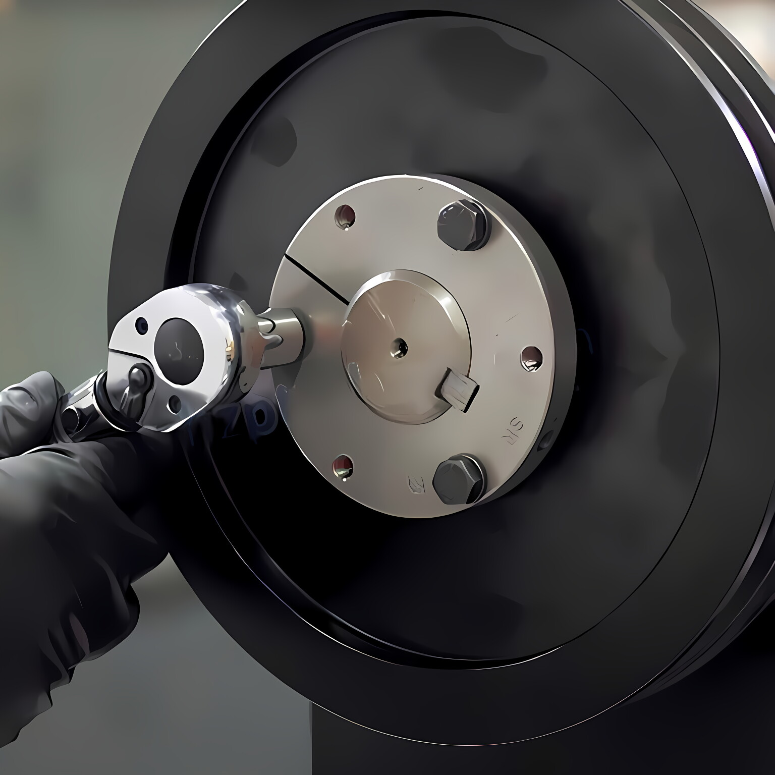 4. Install the key in the keyway of the shaft, install the tapered sleeve of the pulley on the post, and position it, allowing the pulley to move slightly axially when it is locked. Note: When installing a pulley on a vertical shaft, take precautions to prevent the pulley or taper from falling off during installation.5. Tighten the mounting screws alternately until the tapered surface of the pulley and the tapered sleeve are entirely fitted. NOTE: Do not use a worn hex wrench as it may cause loose fitting or damage to the mounting screws.6. Check alignment and pulley runout (swing); correct if necessary.7. Continue to alternately tighten the mounting screws to the recommended shrinking torque value of the mounting screws, as shown in Table 1, and do not apply additional force after reaching the recommended tightening torque value of the mounting screws.8. To increase the gripping force of the taper sleeve, tap the end face of the taper sleeve moderately with a hammer through the pad iron or sleeve. Note: Do not hit the taper sleeve directly with a hammer.9. Tighten the taper sleeve mounting screws again after tapping.10. Re-check the torque after the first test run, and check it regularly in the future. If it is loose, repeat steps 5-9.
Address
Luotuo Industrial Area, Zhenhai District, Ningbo City, China
Tel


 Raydafon