

")
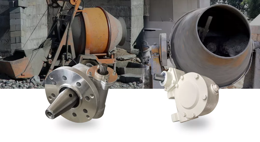
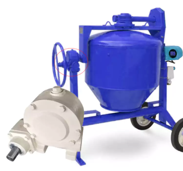 In Cement Mixers, Innovative Drive System Gearbox reducers are typically located at the bottom or side of the mixer, directly connected to the mixing drum. The specific location depends on the design type and structural layout of the mixer. For example, in a self falling mixer, the gearbox may be directly connected to the drive shaft of the mixing drum; In a forced mixer, it may be connected to the driving device of the mixing blade through transmission mechanisms such as chains and belts.
 1. Input shaft 2. Oil seal 3. Deep groove ball bearing 4. Door cover 5. Deep groove ball bearing 6. Hexagonal head bolt 7. Flat key 8. Worm gear 9. Oil plug screw 10. Box 11. Flat key 12. Bevel gear 13. Circlip 14. Shim 15. Worm 16. Deep groove ball bearing 17. Circlip 18. Oil seal 19. Spline shaft 20. Oil seal 21. Retaining ring 22. Door cover 23. Spline sleeve
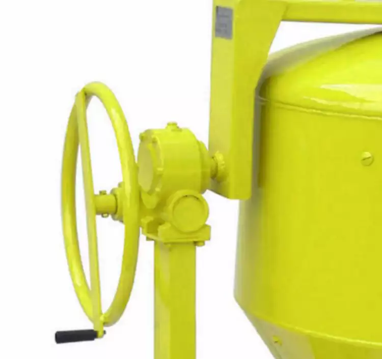
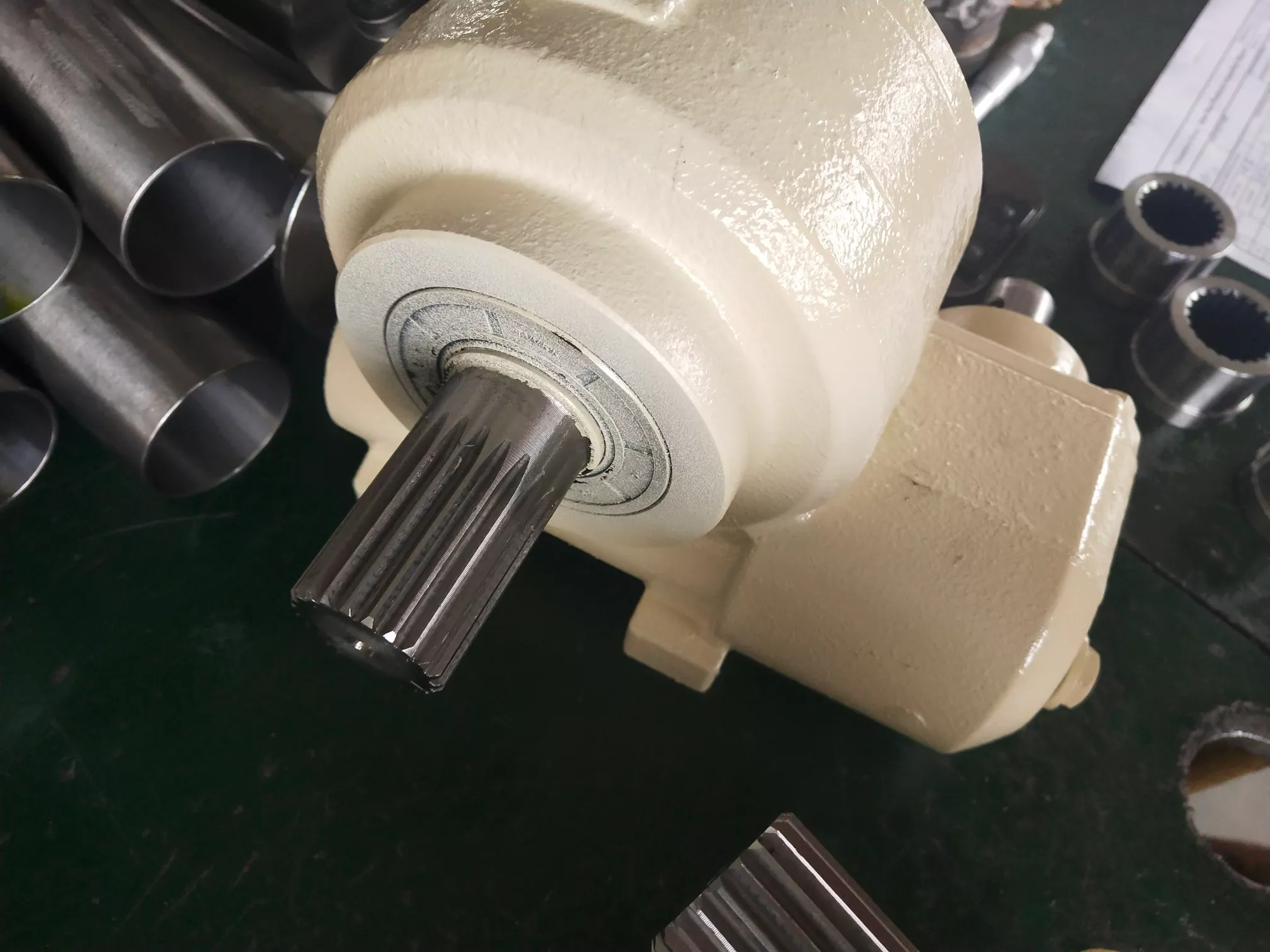
the gearbox in a concrete mixer works by converting the high-speed rotational motion from an engine or electric motor into slower, more powerful torque that is necessary to rotate the mixing drum effectively. Here's how it operates:
Torque Conversion: When the input shaft turns, it causes the smaller gear to turn. Since the larger output gear is connected to the smaller one, it also turns but at a slower rate due to the difference in the number of teeth between the two gears. This reduction in speed increases the torque available to turn the heavy concrete mixer drum.
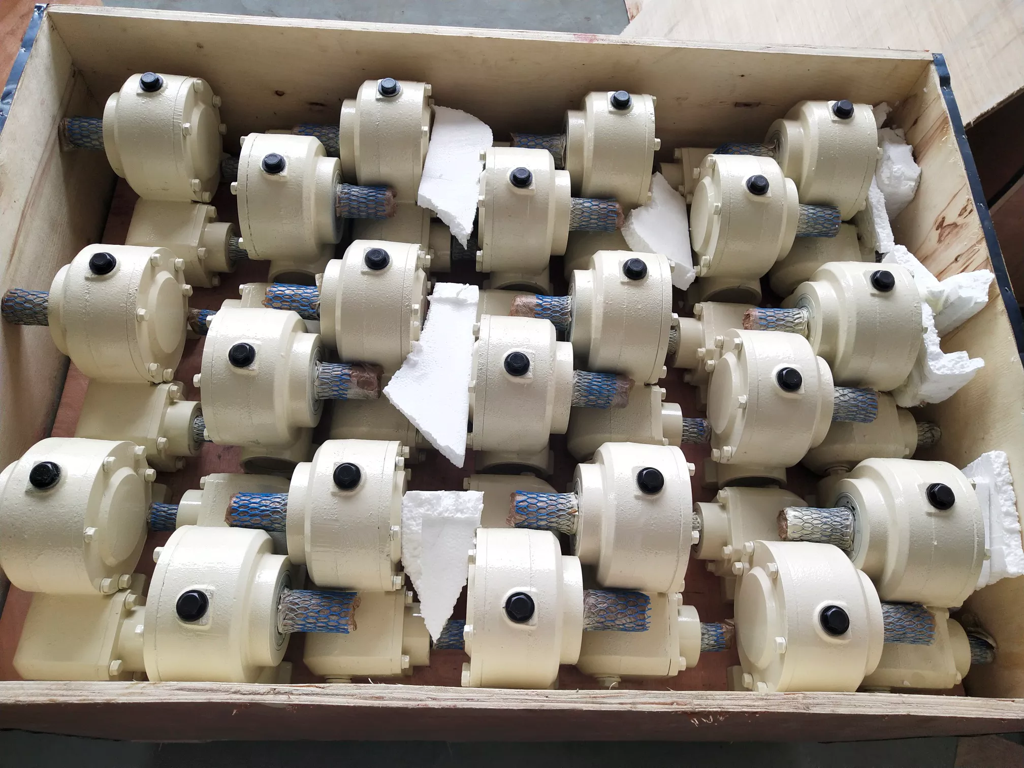 |  |
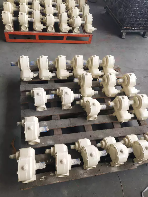
 We have various gearboxes for construction machinery; welcome to inquire from us.
 Address
Luotuo Industrial Area, Zhenhai District, Ningbo City, China
Tel


 Raydafon