


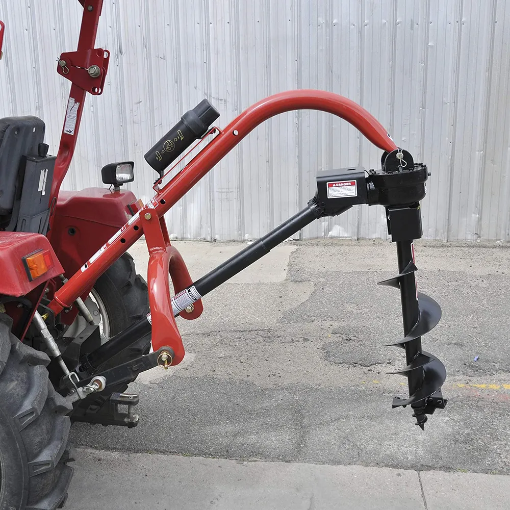
Model 400 3 Point Post Hole Digger for Compact/Sub-Compact/Cat 0 Tractors
The Model 400 3 point post hole digger is a farming equipment used for digging holes for fence posts, signposts, or any other job that requires digging deep holes in the ground. It is specifically designed to be attached to the back of a tractor or a tractor-like vehicle, which provides the necessary power to operate it. The Model 400 3 point post hole digger consists of a heavy-duty steel frame with a gearbox that connects the digger's auger to the tractor’s power take-off. It has a 3-point hitch that attaches to the tractor's hydraulic system to raise and lower the digger to the desired position. The auger is a spiral-shaped drill bit that rotates as the tractor’s engine turns the power take-off shaft. The rotation of the auger creates a hole in the ground as it goes deeper and deeper. The Model 400 3 point post hole digger comes in different configurations with various auger sizes, depending on the job's requirements. Using the Model 400 3 point post hole digger requires a skilled operator who has experience in operating farming equipment. The operator must have knowledge of the terrain, soil type, and the necessary depth and width of the hole required for the job. Overall, the Model 400 3 point post hole digger is a reliable and effective tool that saves a lot of time and effort compared to manual digging.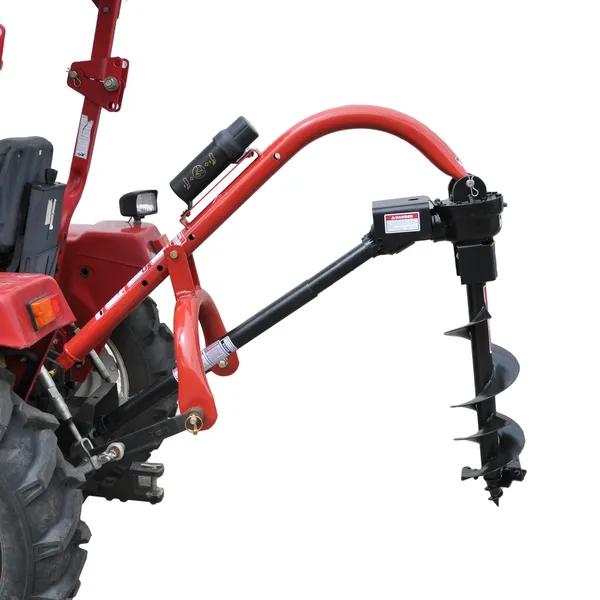
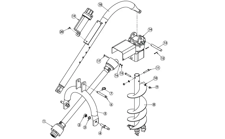
| Model 400 Post Hole Digger | |||
| ITEM # | P/N | Description | QTY |
| 1 | 27-024 | Series 1 Driveline | 1 |
| 2 | 95462A545 | 7/8”- 14 Hex Nut | 2 |
| 3 | 91102A037 | 7/8” Lock Washer | 2 |
| 4 | 43-027 | 7/8” Draw Pin | 2 |
| 5 | 24-0016 | Model 400 A-frame | 1 |
| 6 | 24-0029 | A-frame Pin | 1 |
| 7 | 43-047 | 7/16” LYNCH PIN | 1 |
| 8 | N/A | Compact Auger (Various Sizes) | 1 |
| 9 | 95462A033 | 1/2”-13 Hex Nut | 2 |
| 10 | 91102A770 | 1/2”-13 Lock Washer | 2 |
| 11 | 91247A724 | 1/2”-13 X 3” G5 Bolt | 2 |
| 12 | 98338A230 | 5/32” X 1-1/2” Cotter Pin | 2 |
| 13 | 24-0028 | Boom Pin | 1 |
| 14 | 24-0359 | 45 HP Gearbox with Guards | 1 |
| 15 | 95462A031 | 3/8” -16 Hex Nut | 1 |
| 16 | 91102A760 | 3/8” Lock Washer | 1 |
| 17 | 91247A636 | 3/8”-16 X 3” Bolt, G5 | 1 |
| 18 | 24-0015 | Model 400 Boom | 1 |
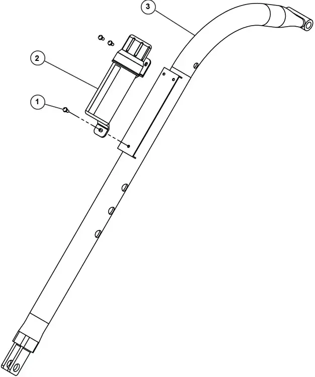
| 19 | 24-0014 | Manual Canister | 1 |
| 20 | 92865A581 | Bolt, 5/16”-18 X 3/4”, Shcs | 3 |
| Model | Model 400 Compact | Model 650 Standard Duty | Model 1000 Heavy Duty | Model 1500 Extra Heavy Duty |
| SKU | 24-0361 | 24-0362 | 24-0318 | 24-0337 |
| Category | 0 & 1 | 1 | 1 | 1 & 2 |
| Boom Length | 56" | 60" | 72" | 72" |
| Tubing Diameter | 2-7/8" | 2-7/8" | 2-7/8" | 3-1/4" |
| Draw Pin Width | 20" | 27" | 27" | 32-1/2" |
| Drive ine | Series 1 | Series 1 | Series 4 | Series 4 |
| Gearbox | 2.9:1 | 2.9:1 | 2.9:1 | 3.18:1 |
| Auger Diameters | 6", 9", 12" (3' lengths) | 6", 9", 12" | 6", 9", 12", 18", 24" | 6", 9", 12", 18", 24" |
| Weight | 150 bs | 160 bs | 200 bs | 235 bs |
| SKU | 24-0361 | 24-0362 | 24-0318 | 24-0337 |
| Features | 4 Positions | 3 Positions | 4 Positions | 4 Positions |
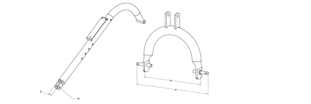
| Model # / CAT | A(in) Lower Hitch Point Spread -Max | B(in) Lower Hitch Point Spread -Min | C(in) Clevis/ Ball Joint Outside Width | D(in) Upper Hitch Point Pin Dia |
| Model 400 / CAT 0, Sub Compact | 26-3/8 | 20-7/8 | 1.75 | 0.75 |
| Model 650 / CAT 1 | 33-1/2 | 28 | 1-5/8 | 1.0 |
| Model 1000 / CAT 1 | 32-3/8 | 26-7/8 | 1-5/16 | 0.75 |
| Model 1500 / CAT 1 & 2 | 38-3/8 | 32-7/8 | 1-5/16 | 0.75 |
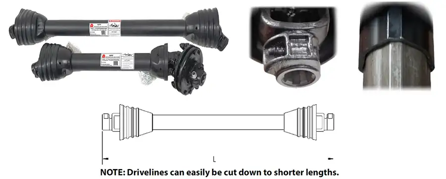
| Series | Shortest Length | Extended Length | Tractor End | Implement End | Common Uses | SKU |
| 1 | 27 | 34 | 1-3/8" x 6 QD | 1-3/8" x 6 QD | Fertilizer Spreader | 27-010 |
| 3 | 40 | 54 | 1-3/8" x 6 QD | 1-3/8" x 6 QD | Finishing Mower, Tiller | 27-011 |
| 4 | 30 | 40 | 1-3/8" x 6 QD | 1-3/8" Round | Finishing Mower, Tiller | 27-012 |
| 4 | 32 | 42 | 1-3/8" x 6 QD | 1-3/8" Round | Rotary Cutter | 27-013 |
| 4 | 36 | 43 | 1-3/8" x 6 QD | 1-3/8"x6 Clutch | Rotary Cutter, Tiller | 27-014 |
| 4 | 37 | 50 | 1-3/8" x 6 QD | 1-3/8" Round | Rotary Cutters, Pond | 27-015 |
| 4 | 42 | 58 | 1-3/8" x 6 QD | 1-3/8" Round | Post Hole Digger | 27-016 |
| 4 | 48 | 65 | 1-3/8" x 6 QD | 1-3/8" x 6 QD | Post Hole Digger | 27-017 |
| 4 | 53 | 74 | 1-3/8" x 6 QD | 1-1/4" Round | Post Hole Digger | 27-018 |
| 5 | 42 | 57 | 1-3/8" x 6 QD | 1-3/8" Round | Rotary Cutters | 27-019 |
| 12 | 48 | 64 | 1-3/8" x 6 QD | 1-1/4" Round | Heavy Duty Digger | 27-020 |
| 14 | 37 | 49 | 1-3/8" x 6 QD | 1-3/8" Round | Post Hole Digger | 27-021 |
| 14 | 56 | 77 | 1-3/8" x 6 QD | 1-3/8" Round | 5' & 6' Pull Cutters | 27-022 |
|
|
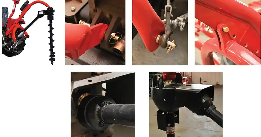
 Step 3: Attach the 7/8” lock washer 3, 7/8” hex nut 2, and draw pin 4 to the “A” frame 5. For the model 650 digger, Category 1 tractors (lift arm spacing of 26”), use the pins in the inward position. For Category 2 tractors (lift arm spacing of 32”), the pins should point outwards.
 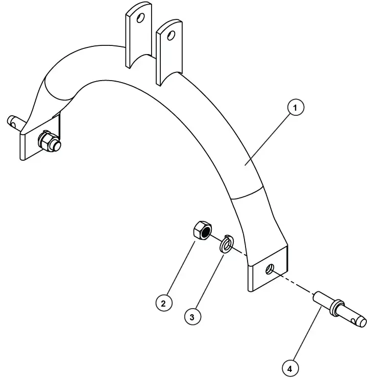 Step 4: Connect the “A” frame assembly 2 to the tractor’s 3-point lift arms. Attach boom assembly 1 to the tractor. Attach the “A” frame 2 to the boom 1 using pin 3 and lynchpin 4 The size of your tractor and auger will determine which hole will work best for the angle adjustment. After complete assembly, the “A” frame to boom location might need to be changed, with the tractor lift arms raised the auger should be no more than 6″ off the ground.
 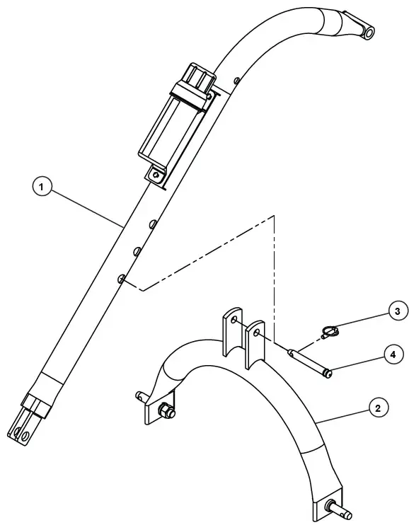 Step 5: Attach the 3 point post hole digger gearbox 1 to the boom using the boom pin 2 and secure it with cotter pins 3.
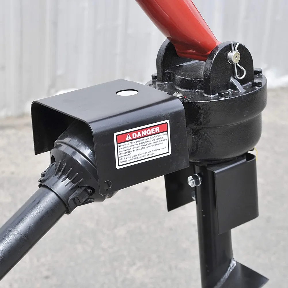
 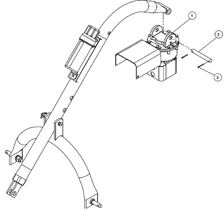 Step 6: Attach the driveline 1 to the 3 point post hole digger gearbox input shaft using the hex bolt 3/8” x 3″ G5 2, 3/8” lock washer 3, and 3/8”-16 hex nut 4. Insert the ¼”x 3/8” set screw in the hole on the yoke that aligns with the 3/16” groove on the gearbox input shaft. Tighten loosely. Attach the tractor end of driveline 1 to the tractor PTO shaft. Retract the yellow zinc-plated outer collar and slip it on the splined PTO shaft of the tractor. Release the collar when it is securely in place on the shaft. The driveline has a 1-3/8×6 spline for the tractor end. PTO adaptors or extenders are not recommended. Attention:
the hex bolt 3/8″-16 x 3″ G5 2 provides shear protection. Use a grade 2 or grade 5 bolt only to avoid damage to the gearbox or auger. Important Note:
The universal joint should be greased with a quality-grade chassis lube approximately every 6 months. At the beginning of each season grease the sliding driveshaft members with moly grease. All diggers are equipped with quick-detach universal joints on the power-take-off end for a 1-3/8 in. splined shaft.
Step 6: Attach the driveline 1 to the 3 point post hole digger gearbox input shaft using the hex bolt 3/8” x 3″ G5 2, 3/8” lock washer 3, and 3/8”-16 hex nut 4. Insert the ¼”x 3/8” set screw in the hole on the yoke that aligns with the 3/16” groove on the gearbox input shaft. Tighten loosely. Attach the tractor end of driveline 1 to the tractor PTO shaft. Retract the yellow zinc-plated outer collar and slip it on the splined PTO shaft of the tractor. Release the collar when it is securely in place on the shaft. The driveline has a 1-3/8×6 spline for the tractor end. PTO adaptors or extenders are not recommended. Attention:
the hex bolt 3/8″-16 x 3″ G5 2 provides shear protection. Use a grade 2 or grade 5 bolt only to avoid damage to the gearbox or auger. Important Note:
The universal joint should be greased with a quality-grade chassis lube approximately every 6 months. At the beginning of each season grease the sliding driveshaft members with moly grease. All diggers are equipped with quick-detach universal joints on the power-take-off end for a 1-3/8 in. splined shaft. 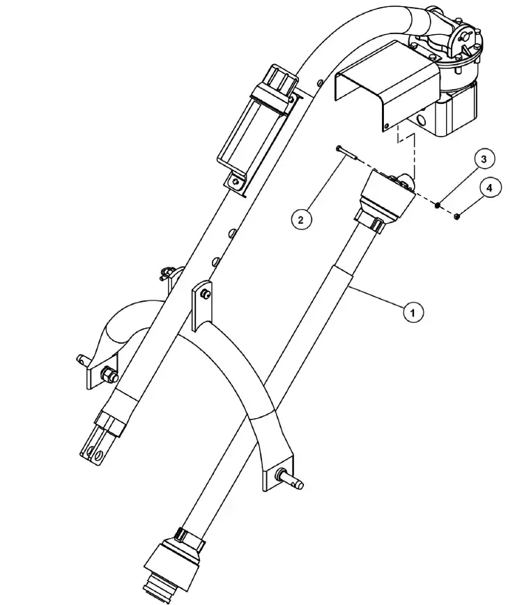 Step 7: Attach the auger 1 to the output shaft on the bottom of the 3 point post hole digger gearbox using the hex bolts 1/2″-13×3″ 4, ½” lock washer 3, and ½” hex nut 2. Tighten the hardware.
 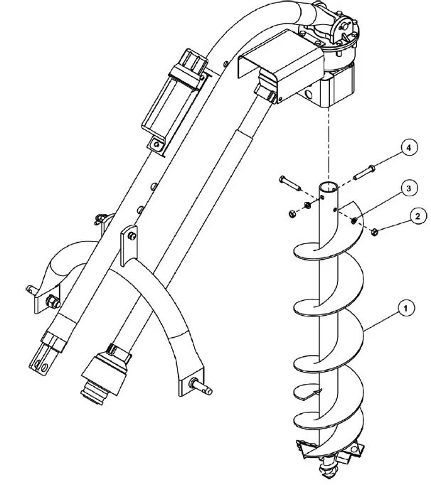 NOTE:
NOTE:
Address
Luotuo Industrial Area, Zhenhai District, Ningbo City, China
Tel


 Raydafon