
Every engineer and procurement professional has faced the dreaded moment: a critical machine sits idle because the gearbox failed, or worse, the newly installed Worm Gearbox doesn’t deliver the expected torque. The production line stalls, costs mount, and the pressure to find a fix is overwhelming. The root cause often boils down to one overlooked factor: How to choose the right worm gearbox for your project? It’s a question that seems simple until you’re buried in catalogues full of ratios, centre distances, and efficiency curves. The wrong choice means overheating, excessive wear, and premature failure. At Raydafon Technology Group Co., Limited, we’ve spent decades helping buyers cut through the noise, matching applications to the exact gearbox needed—whether for a conveyor in a dusty factory or a precision lifting system in a food-processing plant. This guide walks you through a proven, step-by-step method to evaluate worm gearboxes, avoiding the common traps and securing long-term reliability. You’ll learn how to balance torque, speed, mounting, and environment while keeping total cost of ownership in check. By the end, you’ll see how partnering with a manufacturer that truly understands power transmission can turn a complex selection into a straightforward decision.
Imagine you are specifying a gearbox for a bottling line conveyor. The system runs 16 hours a day, must start smoothly under full load, and cannot tolerate slipped timing. One purchasing manager we worked with selected a unit based solely on motor horsepower—only to see the output shaft shear within a week. The root cause was an underestimation of peak torque during frequent start-stop cycles. Worm gearboxes excel at handling shock loads, but only when sized correctly for both nominal and peak torque. Always calculate the equivalent continuous torque, factoring in acceleration, braking, and any load spikes. Raydafon Technology Group Co., Limited provides detailed torque charts for each model, covering service factors for different application classes. Below is a typical comparison table to guide initial sizing.
| Application Class | Service Factor | Typical Daily Hours | Example |
|---|---|---|---|
| I (Uniform) | 1.0 | 3–5 | Light-duty conveyor |
| II (Moderate Shock) | 1.25 | 8–10 | Bottling line, mixer |
| III (Heavy Shock) | 1.5–2.0 | 16–24 | Crusher, hoist |
Selecting the correct service factor prevents overheating and surface fatigue. Pair your load data with a safety margin, and you’ll eliminate the most common failure mode right at the design stage.
A packaging machine OEM once approached us because their prototype indexing table moved erratically. The issue wasn’t the motor—it was a mismatched gear ratio that caused the output to rotate too fast, losing positional accuracy. Worm gearboxes are inherently capable of high single-stage reductions, typically from 5:1 up to 100:1, making them ideal for applications needing slow, precise movement. Yet many buyers default to “the highest torque” without verifying the actual output speed required. You need to determine the exact RPM at the driven shaft and then divide the motor’s nominal speed by that value to find the target ratio. Raydafon Technology Group Co., Limited engineers often recommend a slightly higher ratio if the load includes inertia, as it provides better control and braking. The table below shows how common ratios map to typical uses.
| Ratio Range | Output Speed at 1400 rpm Input | Ideal Application |
|---|---|---|
| 5:1 – 15:1 | 280 – 93 rpm | Agitators, low-precision conveyors |
| 20:1 – 40:1 | 70 – 35 rpm | Indexing tables, small hoists |
| 50:1 – 100:1 | 28 – 14 rpm | Gate drives, winches, stage curtains |
A correct ratio ensures you are not only meeting speed targets but also staying within the gearbox’s thermal and mechanical limits over the full duty cycle.
Common question: “How to choose the right worm gearbox for your project when efficiency drops under heavy use?” The answer lies in understanding that worm gearboxes generate significant sliding friction, converting a portion of input power into heat. Efficiency can range from 50% to over 90%, inversely related to the reduction ratio. If you ignore heat buildup, oil viscosity breaks down, and components gall. For continuous-duty applications, always check the thermal capacity of the housing. It’s not unusual for a well-sized unit to require an external fan or cooling ribs. Raydafon Technology Group Co., Limited addresses this by offering enhanced cooling designs and synthetic lubricants that maintain film strength at elevated temperatures. When sizing, calculate the expected heat generation and match it to the gearbox’s thermal rating, which is often listed in kW at a given ambient temperature. This step alone can double the service life.
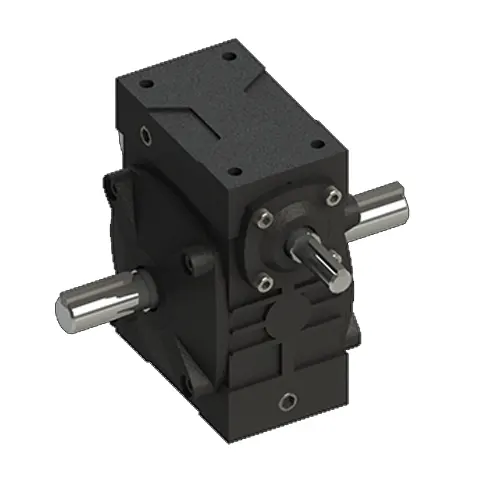
During a plant revamp, a maintenance team struggled to fit a replacement worm gearbox into a tight under-conveyor cavity. The original footprint was no longer available, and off-the-shelf units wouldn’t align with the existing shaft. Worm gearboxes come in various mounting configurations—foot-mounted, flange-mounted, hollow shaft, or torque-arm. Each influences load distribution on the bearings. Outline the space available for the gearbox, motor adapter, and any coupling. Also consider the overhung load created by sprockets or pulleys; exceeding the allowable radial force is a leading cause of output shaft breakage. Raydafon Technology Group Co., Limited pre-engineers adapters and flange interfaces to simplify integration. Before you order, request the manufacturer’s dimensional drawings and compare them against your CAD model to confirm that breather plugs, oil fill, and drain ports will remain accessible.
A food processing plant encountered repeated bearing failures caused by washdown moisture seeping past standard seals. They assumed all worm gearboxes were sealed equally, but material and seal specification vary dramatically. Bronze worm wheels paired with hardened steel worms provide the best wear resistance and friction characteristics. Look for units with dual spring-loaded lip seals on both input and output shafts, and in corrosive environments, opt for stainless steel hollow outputs and epoxy-coated housings. The lubricant also matters: polyalphaolefin (PAO) synthetic oils greatly extend change intervals. Raydafon Technology Group Co., Limited offers a range of configurable sealing options, including Viton and PTFE variants, ensuring that even in high-pressure spray-down zones, the gearbox internals remain protected. A quality material specification directly translates into years of trouble-free operation.
Another key question: “How to choose the right worm gearbox for your project when the ambient temperature fluctuates from -20°C to 50°C?” Temperature swings affect oil viscosity and thermal expansion. The solution is to select a gearbox rated for the extreme ends of your operating range, often requiring synthetic low-temperature grease or a heater band for cold starts. At the hot end, ensure the unit’s thermal capacity derates accordingly. Raydafon Technology Group Co., Limited provides detailed application engineering support to map your exact ambient conditions and duty data, delivering a gearbox that will start reliably even after a freezing night and run cool on a summer afternoon.
By now you have a practical roadmap: define real torque loads, lock in the ratio that gives the precise output speed, verify thermal and mounting constraints, and insist on quality materials. Every project presents its own set of challenges, but the core selection steps remain the same. When you work with Raydafon Technology Group Co., Limited, you’re not just buying a gearbox—you gain a technical partner that audits your requirements, suggesting alternative configurations that often reduce cost without sacrificing performance. Whether you need a single prototype or a annual contract for OEM production, our team will help you navigate the options quickly. Have a current project you’d like us to review? Leave a comment below with your speed and torque targets, and we’ll reply with a preliminary recommendation within one business day. Your next reliable installation starts here.
Raydafon Technology Group Co., Limited is a global manufacturer of worm gearboxes and geared motors, committed to solving our customers’ toughest power transmission challenges. With engineering centres and production lines certified to ISO 9001, we combine European design principles with competitive lead times. Our application experts work directly with purchasing managers and design engineers to specify the exact model required, eliminating guesswork and reducing total acquisition cost. Explore our full portfolio and request a custom consultation at www.raydafongroup.com or reach our technical sales team directly at [email protected].
Li, H. & Zhang, Q., 2021, “Optimisation of worm gear tooth geometry for enhanced film thickness”, Tribology International, 154.
Rossi, L., 2019, “Thermal capacity modelling of worm gearboxes in intermittent duty”, Mechanism and Machine Theory, 135.
Chen, X., 2020, “Frictional power losses in bronze/steel worm drives: an experimental study”, Wear, 448–449.
Yilmaz, M. & Duran, H., 2018, “Life prediction of worm gear sets under variable loading”, Journal of Mechanical Design, 140(7).
Patel, R., 2022, “Influence of lubricant rheology on worm gear efficiency”, Lubrication Science, 34(2).
Niemann, G. & Winter, H., 2017, “Machine Elements: worm gears for industrial applications”, Springer, Vol. III.
Müller, R., 2020, “Acoustic emission monitoring for early fault detection in worm gearboxes”, Mechanical Systems and Signal Processing, 142.
Koizumi, T., 2019, “Effect of misalignment on contact pattern and fatigue life of worm gears”, International Gear Conference, Lyon.
Johnson, S., 2021, “New surface hardening techniques for improved worm gear durability”, Surface and Coatings Technology, 410.
Choi, U. & Park, J., 2023, “CFD analysis of oil flow and churning losses inside a worm gearbox”, Journal of Thermal Science and Engineering Applications, 15(4).

 Raydafon