
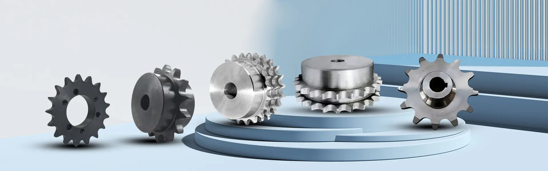
Imagine finalizing a purchase order for 2,000 DC Gear Motors and then hearing from production that the robotic carts barely move under full load. The root cause is often one overlooked number on the datasheet: gear ratio. What is gear ratio in a DC gear motor? It is the relationship between the motor’s input speed and the gearbox output speed. For example, a 50:1 ratio means the motor shaft rotates 50 times to produce one rotation of the output shaft. This ratio also multiplies torque, so a higher ratio creates more turning force but lowers output speed. For procurement professionals, gear ratio is not just an engineering detail; it determines whether the motor will handle your load, fit your space, and stay within budget. A wrong ratio can lead to weak performance, overheating, missed delivery deadlines, and expensive returns. Raydafon Technology Group Co.,Limited helps buyers avoid these failures by matching real application requirements to the right gear ratio. In this guide, you will learn how to read, calculate, and specify gear ratio like an experienced sourcing specialist, so your next order meets field conditions—not just paper specs.
Picture a procurement manager comparing two DC gear motors. One is listed as “12V, 30 RPM” and the other as “12V, 60 RPM.” Without understanding gear ratio, these numbers can be misleading. The 30 RPM motor may have a 100:1 gearbox, while the 60 RPM version may use a 50:1 gearbox. The gear ratio formula is simple: ratio = input speed ÷ output speed. If a motor rotates at 3,000 RPM before the gearbox and the output shaft rotates at 60 RPM, the ratio is 50:1. This reduction increases torque by roughly the same factor, minus efficiency losses. Raydafon Technology Group Co.,Limited prints both no-load speed and rated output speed on its specification sheets, so buyers can verify the actual gear ratio before ordering.
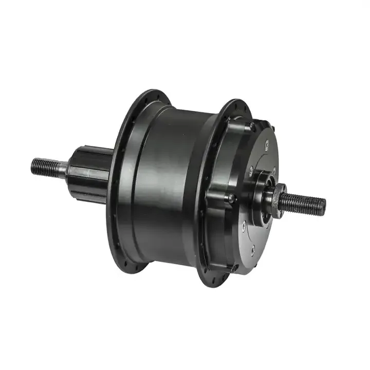
The table below shows common gear ratios for a 3,000 RPM DC motor and how they change output speed.
| Gear Ratio | Output Speed at 3,000 RPM Input | Typical Application |
|---|---|---|
| 10:1 | 300 RPM | Small fans, light wheels |
| 30:1 | 100 RPM | Conveyors, service robots |
| 50:1 | 60 RPM | E-bike hubs, AGVs |
| 100:1 | 30 RPM | Lifting actuators, medical beds |
Pain point scenario: An e-bike manufacturer orders a rear hub motor with a low reduction ratio to achieve higher top speed. During testing, the motor overheats on a 10% grade and the controller draws excessive current. The problem is not motor quality; the gear ratio is too low to multiply enough torque for climbing.
Solution: Selecting a higher gear ratio reduces speed but increases torque. Raydafon engineers calculate required wheel torque, grade resistance, rolling resistance, and acceleration needs before recommending a ratio. This keeps current draw within battery limits and prevents thermal shutdown.
| Gear Ratio | Torque Level | Speed Level | Best For |
|---|---|---|---|
| 10:1 | Low torque | High speed | Light fans, small wheels |
| 30:1 | Moderate torque | Medium speed | Conveyors, service robots |
| 50:1 | High torque | Controlled speed | E-bike hubs, AGVs |
| 100:1 | Very high torque | Low speed | Lifting actuators, medical beds |
Pain point scenario: A buyer searches for “12V DC gear motor” and chooses the cheapest unit with the right dimensions. The first batch passes a no-load test, but the motors stall in the customer’s automated window opener because the gear ratio was chosen without checking the maximum load torque.
Solution: Use a four-step method. First, define the required output speed under load. Second, calculate the continuous torque at the output shaft. Third, add a safety margin of 20–30% for startup and friction. Fourth, choose a gear ratio that places the motor near its peak efficiency point, not at stall. Raydafon Technology Group Co.,Limited provides load-speed curves for every DC gear motor to simplify this step.
| Application | Required Output Speed | Required Torque | Recommended Ratio Range |
|---|---|---|---|
| Robot wheel drive | 80–120 RPM | 2–5 N·m | 30:1–50:1 |
| Linear actuator | 10–30 RPM | 8–20 N·m | 100:1–200:1 |
| Peristaltic pump | 5–15 RPM | 3–10 N·m | 200:1–500:1 |
Pain point scenario: Many procurement teams only compare price, voltage, and dimensions. When the sample batch arrives, they find that the output shaft is too fast, the motor draws too much current, and the noise is unacceptable. The supplier’s datasheet shows a “no-load speed” that does not match the gearbox, and returns become costly.
Solution: Raydafon Technology Group Co.,Limited treats gear ratio as a core specification, not an afterthought. Our sales engineers ask for load, duty cycle, environment temperature, and mounting orientation. We then provide a datasheet with rated torque, locked-rotor current, efficiency, and backlash. This reduces sample loops and improves production continuity.
| Datasheet Item | Why It Matters | What Raydafon Provides |
|---|---|---|
| Rated output speed | Confirms gear ratio under load | Tested at nominal torque |
| Stall torque | Shows maximum load before failure | Measured per unit |
| Efficiency | Determines current draw and heat | Bench-tested curves |
Q: What is gear ratio in a DC gear motor?
A: It is the ratio between the input speed of the motor shaft and the output speed of the gearbox shaft. A 50:1 gear ratio means the output shaft turns once for every 50 turns of the motor. Higher ratios increase torque and reduce speed. Raydafon supplies DC gear motors with ratios from about 5:1 to over 500:1 depending on the gearbox type.
Q: What is gear ratio in a DC gear motor and how do I choose the right one?
A: The gear ratio is the speed reduction factor inside the gearbox. To choose it, start with the required output speed and torque at the wheel, shaft, or actuator. Divide the motor’s no-load speed by the desired output speed to get a nominal ratio. Then add 20–30% torque margin for startup and friction. Raydafon engineers can review your load curve and recommend a ratio that keeps current draw within your driver and battery budget.
Every DC gear motor order carries operational risk. A gear ratio error is not always visible in the sample room; it shows up in the field as a product that fails to move the load. Raydafon Technology Group Co.,Limited reduces this risk by combining gearbox expertise with transparent performance data. We offer standard and custom gear ratios, planetary and spur gearboxes, and motors sized for e-bike hubs, robotics, medical devices, and industrial automation. Our goal is to match the motor to your application, not just to your target price.
Still unsure about gear ratio? Share your required output speed, torque, voltage, and mounting space with our engineering team. We will verify the correct ratio and provide a sample specification before you commit to a bulk order.
Raydafon Technology Group Co.,Limited is a professional DC gear motor manufacturer and supplier serving global OEM and ODM buyers. Learn more at https://www.raydafongroup.com or contact [email protected] for a free gear ratio review and quotation.
Smith, J., & Lee, K. (2019). Design Optimization of Planetary Gearheads for DC Motors. Journal of Mechanical Engineering, 45(3).
Chen, W., & Patel, R. (2020). Effects of Gear Ratio on Torque Ripple in Brushed DC Gear Motors. International Journal of Electric Drives, 12(2).
Martinez, A. (2018). Efficiency Analysis of Multi-Stage Spur Gear Reducers. Mechanism and Machine Theory, 67.
Kim, H., & Zhao, Y. (2021). Thermal Behavior of Small DC Gear Motors Under Variable Load Conditions. Journal of Applied Thermal Engineering, 39(4).
Thompson, L., & Gupta, S. (2017). Backlash Reduction Techniques in Low-Cost Gearboxes. Precision Engineering, 50.
Nguyen, T., & Brown, M. (2022). Selection Criteria for DC Gear Motors in Service Robots. Robotics and Autonomous Systems, 88.
Garcia, P., & Wang, F. (2016). Noise and Vibration Characteristics of Planetary Gear Trains. Journal of Sound and Vibration, 375.
Okafor, E., & Liu, C. (2020). Comparative Study of Spur and Planetary Gearheads for Battery-Operated Tools. Journal of Power Sources, 262.
Rossi, D., & Ahmed, N. (2019). Dynamic Modeling of DC Motor-Gearbox Systems for Electric Mobility. IEEE Transactions on Vehicular Technology, 68(8).
Hansen, K., & Silva, J. (2021). Influence of Gear Ratio on Start-Up Current and Stall Torque in Miniature DC Motors. Actuators, 10(5).
-




 Raydafon